


Please Leave Us A Message
Privacy statement: Your privacy is very important to Us. Our company promises not to disclose your personal information to any external company with out your explicit permission.
 February 24, 2023
Abstract: Controlling the junction temperature of LEDs to a certain range is the key to ensuring the lifetime and luminous efficiency of LED lamps. In this paper, the measurement method of LED junction temperature is discussed. It is proposed to measure the junction temperature of LED light source in real time through single-chip microcomputer. When the junction temperature exceeds the set value, the PWM signal is generated to adjust the output power of the power supply. The power supply schematic diagram and single-chip program block diagram based on junction temperature protection using LM3404 and PIC12F675 are given. Tests have shown that LED Driver based on junction temperature protection can effectively improve the reliability of LED lamps.
0 Preface
With the advancement of LED epitaxial materials, chip technology and packaging technology, the luminous efficiency of LEDs continues to increase, which makes it possible to replace traditional light sources with LED light sources. In theory, LED has the advantages of long life and high efficiency, but in some practical applications, it has left the impression of large light decay and short life, which greatly affects the popularity and promotion of semiconductor lighting. The reason is mainly the driving power problem of LED.
Long life and high efficiency of LEDs are premised, that is, suitable working conditions. The main factor affecting the life and luminous efficiency is the working junction temperature of the LED. The test data provided by mainstream LED manufacturers shows that the luminous efficiency of LED is almost inversely proportional to the junction temperature, and the lifetime decreases almost exponentially with the increase of junction temperature. Therefore, controlling the junction temperature within a certain range is the key to ensuring LED lifetime and luminous efficiency. In addition to the heat dissipation measures, it is necessary to incorporate the junction temperature into the control parameters of the driving power supply.
1 LED junction temperature detection
The junction temperature of the LED refers to the temperature of the PN junction. It is difficult to actually measure the junction temperature of the LED, but it can be measured indirectly according to the temperature characteristics of the LED.
The volt-ampere characteristics of LEDs are similar to those of ordinary diodes. Typical volt-ampere characteristics of blue LEDs used for white illumination are shown in Figure 1.
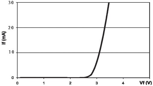
Figure 1 volt-ampere characteristics of LED
The volt-ampere characteristics of LEDs have the same negative temperature coefficient as other diodes, that is, the I/V curve appears to shift left when the junction temperature rises, as shown in the following figure.
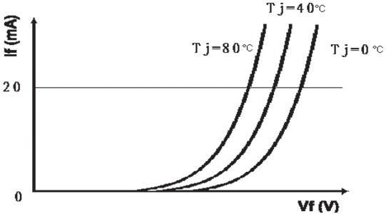
Figure 2 Temperature characteristics of volt-ampere characteristics
Generally, for every 1 °C increase in the junction temperature of the LED, the I/V curve will shift to the left by 1.5~4mV. If the applied voltage is constant, then the current will increase, and the current will only increase its junction temperature. High, even leading to a vicious circle. Therefore, the current LED driving power supply is generally designed to be a constant current power supply.
According to the rule that the I/V curve increases with the junction temperature and the left shift, in the case of constant current supply, the LED junction temperature can be estimated by measuring the forward voltage of the LED.
In practical applications, it is often unnecessary to determine the particularly accurate value of the LED junction temperature. At this time, the estimated value of the junction temperature of the LED light source of the overall luminaire can be determined by the test method. Taking a 12W downlight as an example, the light source part is composed of 4 and 6 strings of medium power LEDs, and the circuit connection form is as follows:
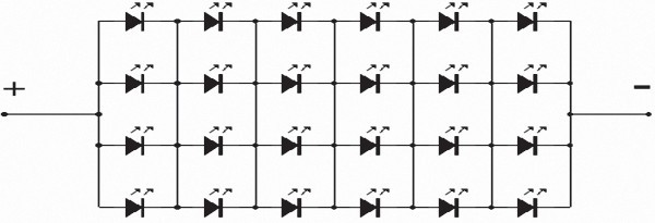
Figure 3 LED light source circuit connection diagram
The test procedure for determining the relationship between the forward voltage and the junction temperature is: 1) placing the light source in the incubator; 2) setting the temperature of the incubator; 3) after the temperature in the incubator is sufficiently balanced and stable, accessing both ends of the light source Constant current source; 4) quickly measure the forward voltage of the light source and record; 5) repeat the above steps 1) ~ (4), the temperature of the incubator from low to high, measured more point data.
According to the above steps, the 12W downlight source is measured three times. The data is as follows:
Table 1 Measurement data of LED forward voltage drop and junction temperature
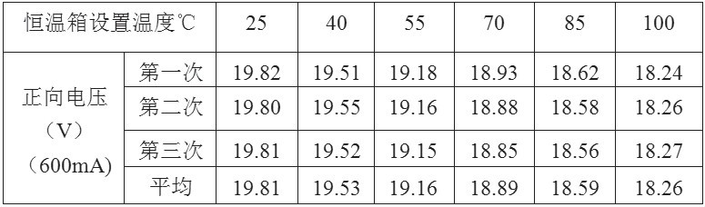
It can be seen from Table 1 that the consistency and regularity of the measured data are obvious.
Due to the short test time, the oven can be set to a temperature approximately equal to the junction temperature of the LED source. In the case of a constant current of 600 mA, it is not difficult to obtain the relationship between the forward voltage of the light source module and the junction temperature by mathematical methods. Using the Excel tool, the temperature is the X-axis, the average is the Y-axis, and the (X, Y) scatter plot is generated. Selecting the linear regression analysis type produces the following trend graph and formula.
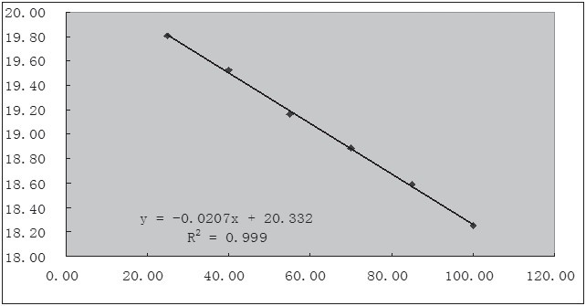
Figure 4 Trend graph generated by Excel
It can be seen that the relationship between the forward voltage and the junction temperature of a light source composed of 4 and 6 strings of medium power LEDs when driven at 600 mA constant current is:
Vf = -0.0207Tj+ 20.332 (1)
Tj= 982.22-48.31Vf (2)
Where Vf is the forward voltage drop of the LED source and Tj is the junction temperature. It should be noted that although the LED products of different specifications of different manufacturers meet the above trend, the specific data has certain differences, so the specification model needs to be retested after replacing the manufacturer.
2 Introduction to LM3404
With the development of LED lighting applications, many domestic and foreign manufacturers have introduced a number of devices for driving LEDs. Among them, National Semiconductor's LM3404 and series products are a constant current driver chip that is very suitable for small and medium power LED light sources.
The LM3404 has a built-in MOS switch with a maximum output current of 1A and an efficiency of up to 95%. The chip is available in an 8-lead SOIC package with one pin that uses a pulse width modulated (PWM) input signal to control the brightness of the LED.
In addition, the chip can provide current sensing with a feedback voltage as low as 0.2V. The input voltage is 6~42V, and its internal circuit structure is shown in Figure 5.
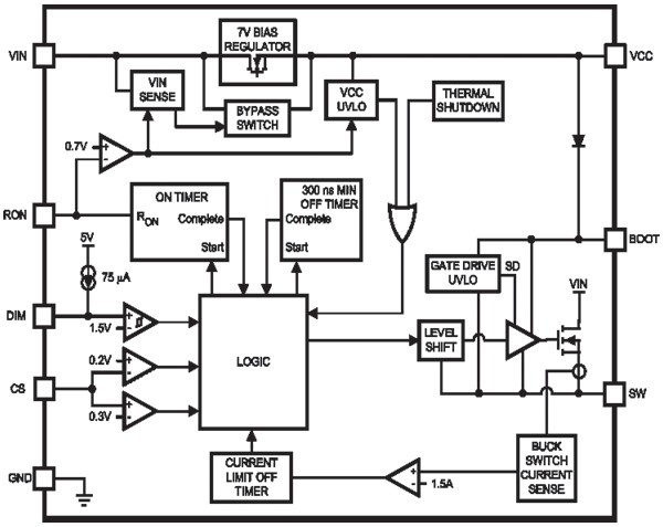
Figure 5 LM3404 internal circuit structure
Pin definition:
SW: the internal MOS tube output terminal, generally requires an external inductor and a Schottky diode;
BOOT: Internal MOS tube start pin, generally connected to the SW terminal with a 10nF capacitor;
DIM: PWM dimming input terminal, the average power of the output can be adjusted by inputting PWM signals with different duty cycles;
GND: ground terminal;
CS: feedback pin for setting the constant current value;
RON: On-line control terminal, this pin is grounded to stop the chip and is in a low power state;
VCC: power supply pin, which is provided with a 7V voltage inside the chip, and a filter capacitor is connected to the ground when applied;
VIN: Input, voltage range 6~42V, range from 6~75V for LM3404H.
The LM3404 application is very simple, a typical application using the LM3404 is shown in Figure 6.
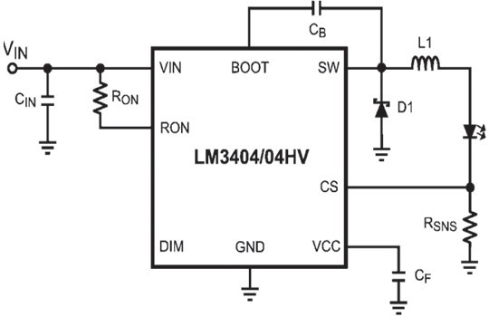
Figure 6 LM3404 typical application circuit diagram
In the figure, Rsns is a sampling resistor, which can be determined according to the design constant current value; Ron generally uses a resistance of about 100k; the switching frequency can be determined; L1 is the output inductor, which can be determined according to parameters such as design ripple and switching frequency.
3 LED Power Supply design based on junction temperature protection
The key to LED driver circuit based on junction temperature protection is junction temperature detection and how to protect it. According to the relationship between the junction temperature and the forward voltage of the LED, the junction voltage of the LED light source can be measured to determine the junction temperature. However, the ripple of the LED constant current driving circuit is large. To avoid false protection, the detection circuit must measure the value. Filtering is performed. On the other hand, when the junction temperature exceeds the set value, the protection measures, such as enabling the light source to reduce the power, the whole lamp is degraded and operated, which is a more reasonable solution. Using a low-power single-chip microcomputer with analog input, the detection data can be digitally filtered, and the power of the LED light source can be adjusted by the PWM output control to simplify the design of the detection circuit and the control circuit.
Microchip's PIC12F675 low-power, in-circuit programmable microcontroller with programmable 4-channel analog input, 10-bit resolution analog-to-digital conversion, built-in watchdog, 4MHz oscillator, 128-byte EEPROM, single-byte instruction system , 8 foot package. Is a simple and practical, cost-effective microcontroller. The forward voltage of the LED light source is sampled and then connected to the analog input end of the PIC12F675. After AD conversion, the coarse error is removed, and the average value of multiple data is taken as the junction temperature judgment basis, and the output PWM signal is used to control the constant current driving chip. The effect of adjusting the output power is achieved.
In addition, an open circuit determination can be made based on the measured values, thereby simplifying the open circuit protection circuit.
For example, a downlight consisting of 4 and 6 strings of medium power LED chips is used. The design has a constant current value of 600 mA and a junction temperature protection point of about 80 ° C. According to equation (1), the source voltage protection point is 18.68. V, that is, when the voltage across the light source is lower than 18.68V, the LED junction temperature will exceed 80 °C, and the driver should take protective measures. The schematic diagram of the LED power supply circuit based on junction temperature protection consisting of LM3404 and PIC12F675 is shown in Figure 7.
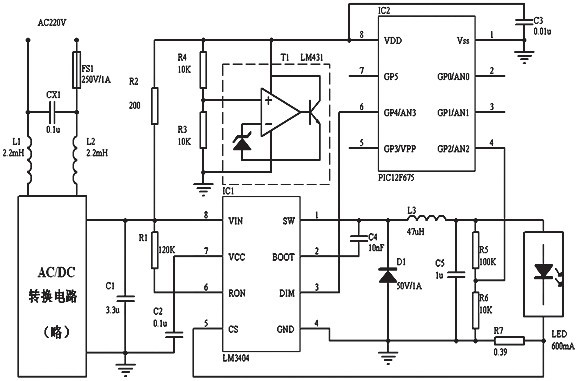 Figure 7 LED power supply schematic based on junction temperature protection
In the schematic diagram, CX1, L1, and L2 form an input EMC filter circuit, which outputs 24V DC through AC/DC conversion. If it is used for battery-powered emergency lighting, solar lighting, and vehicle lighting applications, this part is omitted. R1, LM3404, C4, D1, L3, and R7 form a typical constant current driving circuit. For a light source module composed of power chips of 4 and 6 strings of LEDs, the sampling resistance is 0.39 Ω. R2, R3, R4 and LM431 form a voltage regulator circuit that provides a stable 5V supply and internal AD conversion voltage reference for the PIC12F675.
The output of LM3404 is divided into R5 and R6 and input to analog port AN2 of PIC12F675. PIC12F675 obtains the forward voltage of LED light source through internal AD conversion and calculation, generates PWM signal according to the set value program, and accesses DIM of LM3404 through GP4 pin. The end adjusts its output power.
PIC12F675 initially sets the GP4 output high level. If the LED forward voltage is within a reasonable range, the high level output is maintained to make the LM3404 work normally; if the LED forward voltage is gradually lower and lower than the set value of 18.68V, then The PWM signal is output on the GP4 pin, and its duty cycle can be sequentially decreased until the LED forward voltage is lower than the set value. When the measured LED forward voltage is high, it can be judged that the output is open, and the PIC12F675 can output low level to turn off the output of the LM3404.
It should be noted that the output voltage sampling contains a current sampling voltage of approximately 0.23V for the LM3404 constant current control, which should be adjusted in the calculation procedure of the PIC12F675.
The block diagram of the PIC12F675 is shown in Figure 8.
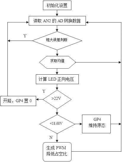
Figure 8 MCU block diagram
4 Conclusion
For the 12W downlight composed of 4 and 6 strings of medium power LEDs, in the test using the above driving scheme, when the artificial hot air is blown to the heat radiating shell or the light source is in contact with the heat radiating shell, the LED light source will be quickly darkened, and the temperature of the light source substrate will follow The drop effectively protects the light source itself. When the luminaire is returned to normal, the brightness of the LED light source will quickly return to normal.
In practical applications, there are many reasons why the junction temperature exceeds the set value, such as a harsh environment, a radiator contact problem, or a fan stall under forced air cooling conditions. An increase in junction temperature will result in a decrease in the forward voltage of the LED source, especially in the case where the source is connected in series by multiple LEDs.
By detecting the forward voltage of the LED light source, indirectly measuring the junction temperature, and using a single chip to adjust the power of the LED light source, the reliability and life of the overall luminaire can be greatly improved. In addition, the LED power supply based on junction temperature protection can easily expand other functions by controlling with a single chip microcomputer. For example, as a street lamp, it can be programmed to reduce the power operation in the middle of the night, thereby further saving energy and extending the life of the lamp; adding other sensors to achieve on-demand illumination; adding a remote communication module can make the lamp constitute an intelligent control network and the like.
The above is the LED driver design based on junction temperature protection we have listed for you. You can submit the following form to obtain more industry information we provide for you.
You can visit our website or contact us, and we will provide the latest consultation and solutions
Send Inquiry
Most Popular
lastest New
Send Inquiry

Privacy statement: Your privacy is very important to Us. Our company promises not to disclose your personal information to any external company with out your explicit permission.
Fill in more information so that we can get in touch with you faster
Privacy statement: Your privacy is very important to Us. Our company promises not to disclose your personal information to any external company with out your explicit permission.