


Please Leave Us A Message
Privacy statement: Your privacy is very important to Us. Our company promises not to disclose your personal information to any external company with out your explicit permission.
 March 02, 2023
This article details how to use the inexpensive 555 timer to control a dedicated LED Driver instead of a microprocessor in some applications that do not require the full functionality of the LED driver. This allows the user to maintain a constant current in the LED driver while reducing overall system cost.
More and more applications are now using LEDs compared to a few years ago. These applications range from high-end video displays to low-end lighting applications. Designers typically only need some of the functionality of a dedicated LED driver, but are unable to afford the associated cost of controlling the microprocessor they need.
Dedicated LED drivers are often designed to be microprocessor controlled and are designed to implement features such as analog or pulse width modulation (PWM) LED current control, independent control of each LED, LED status and fault information reading. These advanced features may not be required for applications that require only constant LED current (eg LED illumination or illumination). In these applications, a 555 timer such as the TLC555 can replace the microprocessor, thereby reducing system cost while achieving precise control of the LED current, independent of input voltage, temperature, and LED forward voltage drop.
For example, the TLC5917 is a dedicated LED driver that controls eight independent constant current sinks. Normally, it requires a microprocessor to drive four digital input signals. The instruction /OE (Allow Output) activates and deactivates the IC. Serial Data Input (SDI) data is clocked into the input shift register of the IC on the rising edge of the clock (CLK). The data in the shift register is transferred to the internal on/off latch on the falling edge of LE (locked). When simple LED on/off control of LED current is required, the following circuit uses the 555 timer that is ubiquitous instead of microprocessor control.
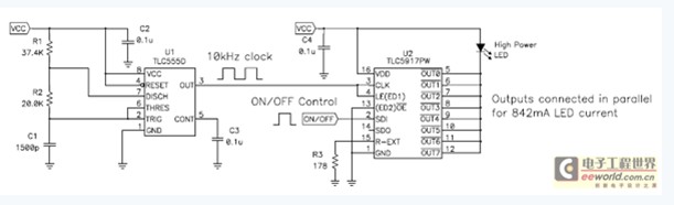
Figure 1 TLC555 timer replaces the microprocessor of the LED driver
The TLC5917 output can drive eight independent LEDs, or it can be connected in parallel to increase current capability to drive a single higher power LED. Its internal current setting register has a default startup value. These values work in conjunction with Rext to set the LED current. In this application, Rext sets the current for each output to IOUT = 18.75A / Rext = 18.75A / 178 ohm = 0.105A. Connect all outputs in parallel to get a LED current of 0.842A.
On power-up, the internal on/off latches turn all outputs on or off to “0” by default, so these latches must be set to “1” before the output is turned on. The 555 timer replaces the microprocessor for this function. Both CLK and LED are connected to the square wave output of the 555 timer. On each rising edge of CLK, the SDI data is shifted into the TLC5917 input shift register. On the falling edge of LE, the data is latched into the on/off latch. Since data transfer and latching occur on different clock edges, the CLK and LE pins can be connected to the same input clock signal. The IC is permanently activated by hardwired/OE ground. SDI can be connected to Vcc to automatically turn on the LED when power is turned on. This connection "1s" is continuously clocked to turn on all outputs. We can also connect SDI to a switch or digital input for LED on/off control. After that, SDI can be pulled to Vcc, and all "1s" are continuously clocked, thus turning on the output. Otherwise it will be pulled to ground and all "0s" will be continuously clocked to turn off the output.
The clock speed of the 555 timer determines the speed of the LED switch. When each LE falling edge latches the SDI data into another eight internal on/off latch, the LED current ramps between 0-100% during eight clock pulses, turning the other eight outputs on or off. Figure 2 shows the resulting stepped LED current that increases and decreases with each successive LE falling edge. Even the relatively slow 10 kHz clock frequency produces a turn-off and turn-off transition of only 0.8mS, which we feel for a moment. Gradual opening and closing can be achieved with a very slow clock frequency. By setting the clock frequency to 0.1 Hz, the LED can be gradually turned on and off within 0.8 seconds.

Figure 2 LED turn-on and turn-off at 10 kHz clock frequency
About the Author
Michael Day is currently Director of Power Management Applications at TI Power Products, with 16 years of design experience in power conversion. Michael is currently responsible for managing the TI DC/DC Power Applications Division. He graduated from Texas Tech University with a BS in Electrical Engineering and a Masters in Electrical Engineering with a research direction in Pulsed Power. Michael is an IEEE member and has published more than 60 papers on power, portable power and lighting.
The above is the Application of 555 timer in LED driver we have listed for you. You can submit the following form to obtain more industry information we provide for you.
You can visit our website or contact us, and we will provide the latest consultation and solutions
Send Inquiry
Most Popular
lastest New
Send Inquiry

Privacy statement: Your privacy is very important to Us. Our company promises not to disclose your personal information to any external company with out your explicit permission.
Fill in more information so that we can get in touch with you faster
Privacy statement: Your privacy is very important to Us. Our company promises not to disclose your personal information to any external company with out your explicit permission.